The critical
description of the machine is: that with proper design, sealing,
and construction, the hydraulic pressures constant in an ocean at depth/ can be used to
create electrical power. The critical
 difference in a working power station or not: is the amount of energy that must be used to transfer the water back into the ocean , at a height above where it enters the machine. That efficiency is to be determined by

mechanical advantage/ and this machine seeks to define a method by which that can be done. The critical construction, and use of that machine relies upon appropriate sealing. IF there is significant efficiency and sealing in the end product: an endless source of electrical power without serious injury to the planet will exist. Other than independent exit valving; there need be, only two significant sealing areas; one at the bottom bearing (not a problem)/ and one at the transition from horizontal pan to vertical piping. A reality of size to be determined by the seal. Or, where the water piping meets the impeller housing, dependent upon design. The alternative is “water tight bearings” for the impeller on the spinning upright shaft: which limits all primary sealing areas to small. The mechanics are then simple and plain. the pool of “calm water”. sits on top of the impeller; generator above water; use your imagination. electricity goes through central shaft piping or through outer wall of of vertical piping, and must be sealed, to rise or fall, on the outside.
More critical: the power used to push the lower turbine that drives the valve train to hydraulically push water back out into the ocean; does not lose its pressure, even though water is going through it to power the impeller that drives the generator. That is because the turbine sits in the energy source itself; and cannot escape the force of that ocean pressure. The valving turbine therefore has the same basic power as the generating impeller; do to the difference in design. The valving turbine converts that pressure into a mechanical lever action. While the water pressure that goes through it; is turned vertical, and imparts most of its energy to the generator impeller. “with a flood of energy available; pressure does not know the difference in direction/ nor does it have to divide” therefore while the valve turbine pushes horizontal; the generator impeller pushes vertical (establishing we don’t need to share).
The action of the turbine is affected by the reaction of the impeller generator. To limit that an additional structural element can be added in to reflect the reaction of the impeller; and retain directional control of the water source. Thereby using structure to control the primary reaction. The valving turbine cups (push points) need the front to be designed for gliding through the water with as little resistance as possible. To accommodate that flow patterns must be studied, and environmental shapes established. kindly pardon the lack of consistent information as two designs begin here; I haven’t thought of this machine for decades (you couldn’t hear it before)/ but, it is enough, if you try to understand. YOU judge in an instant, and never think for yourselves; consequently I aim for “60-70%” clarity; because finding anyone who can think “is a less than ten percent probability”. “you know; you don’t have to think”; because you believe, as the religious all do. your media priests propagate, and the university is your god. So “who cares”? Even so, our world is facing extinction; and you don’t even know it. So, we fight just a bit, and I must defend a bit from the endless armies of thieves; which means not only two machines, but three or four different designs to one; for you to shift through, are here as well. Find a brain, without a thief attached; and I will help you as needed.
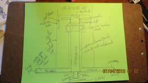
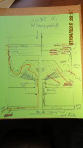
The necessity of understanding is this: that even though water seeks its own height, regardless of the circumstances it is in: that is not what we are doing in this machine. INSTEAD we are taking the pressure, or power out of the water, to use it in generating electricity: which causes the water not to rise, because the pressure is gone. We then create a situation just like an hydraulic jack: which allows us to force small amounts of energy through relatively tiny holes into the positive displacement of the ocean. Gaining a mechanical advantage due to design. In this development: the lower the impeller to drive the generator is in the machine; the more pressure it has to use. A slightly different design than what is pictured is then the reality to be used; but it does become more jumbled up when trying to explain it to those not familiar with mechanics. Basically, the pipe for water entrapment rises above the impeller instead of below it. Whereas the exit valve drive will remain at the level most suited to the work. In this design the spinning shaft ends just above the exit valve drive with a structural bearing, and potential seal, for the entire exit valve drive; so as to pressurize the valving area if desired.
. An option is to include an electric motor drive above the bearing in the rare instance an additional pulse might need to be added to remove the water. The raw power is in the size of the pipe delivering water into the impeller. The pressure is dependent upon depth, and how much energy it takes to push the water back out into sea. Whether seals hold, means it works or not.
The ability to use the ocean or deep water to generate electricity can be accomplished IF: the efficiency is right.
Deep water has far more weight pushing on it; therefore it has energy to consume. The ability to use that energy is reliant upon the design. A pipe column is placed in the water with its open top above the water surface. It sits vertically, and is anchored to the bottom. Like an upside down umbrella: with a turbine inside. The lower bottom construction is like a flat pan enclosed with spinning vanes inside; and directional ports at the circular edge of the pan. That can be closed or controlled. Water is then allowed through the ports/ to push on the vanes, with a mechanical advantage based upon the diameter. That water contained in the outer edge of the vanes, and will flow back to the center structure, through a continuous piping from the edge of the vane, upwards into the spinning support mechanism: where it exits the piping, at a much higher level in the water “ocean”; through common reed style valves. The water then moves up the inner structure of the pipe from deep water to higher, “surface water”: where the difference in energy is extracted by a spinning shaft, upon which the entire machine operates. To achieve the energy available: requires you to remove the water from the column at about half way between entrance of the water, and the atmosphere above the water. This requires correct seals and design properties to keep the water where it needs to be. And would include a sump pump to remove any leakage/ lest it fill the pipe and make the machine useless. A lot of weight, means a lot of energy is available. Better, more fluid descriptions of this machine/ invention; are not going to be given unless we can make an agreement. This is however sufficient to get the point across.
Try not to let the thieves, bastards, traitors, fools, terrorists and the rest steal it from you. To aid and abet that effort: let it be added, other common styles of valving can work. The valving is located on the outside of the pipe, built in such a way as to make replacements simple and easy. While the inside spinning rod is fitted with enclosures and seals; that allow the water in, and is then guided and ramped toward the valving for maximum mechanical effect. These valving enclosures extend upward one on top of the other; with piping interlaced through each division of water removal. The generator sits on top above the water surface; for ease of servicing/ but does not have too. The bigger the diameter pipe: the more force by the absence of that weight of water in the pipe column is available. Just like “size of ship”.
While the energy is available from NOT letting the water rise all the way to the surface; if the mechanics are efficient enough. The size of the tubing from entrance to exit should be kept: many & small, so that major leakage points and hydraulic pressures are minimized. “a few small leaks are better than one big leak”. Smaller pressure ports require far less energy to expel the water. Although if you can build it right, that could be an unnecessary expense. The column, seals and equipment needs to be serviceable; keep it in mind.
The purpose of an enlarged pipe is: to bring the small delivery tubes into the center where the required inertia of mass is limited, and then guide it into the outside wall; using the pressure of centrifugal force to multiply the effect and efficiency of the valving.
The entry ports will need a scraping ring. Either one single ring spinning from the center bearing; either by shaft movement or simply by the movement of the water itself. OR, by flattening the outer portion of each port individual disks can be placed on each individual port, and will spin by water pressure in a perpendicular manner. To clean the miscellaneous realities that would otherwise cause trouble.
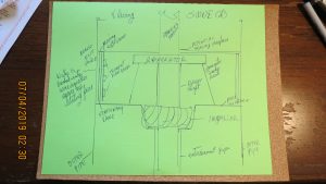
I give you the secondary design as well. Remembering that the energy is found by removing the weight of water above where the water exits. That transforms into usable energy. To aid the efficiency those delivery tubes (or a single delivery tube, massing them together) can be directed into a turbine blade BEFORE it turns to exit the outer structure piping. This collects the energy of that weight plus more; that is being displaced before water turns to exit. Mechanical advantage then does the work of pushing the water through the valves. That turbine either combines with the main shaft or operates a separate generator. Water then exits through two or more horizontal “thinly separated plates, with curved vanes to push the water out (at each level)”; can be used instead of individual tubes at each level. All tolerances are critical. The machine needs “close-able ports” to isolate it. It is flooded to install/ and then pumped out to use. The ability to make seals determines size.
By using thinly separated horizontal plates; the spinning plates can be housed inside stationary top and bottom plates. Which are then able to bring the sealing area back to the center where significantly smaller seals are needed. A three step seal surface, would likely be best.
It is an idea potentially worth even more than the other two/ because it is passive in terms of climate and world; by using what is available. IT DOES generate heat when working; but the water and earth itself will take care of that without serious complaint. Making this a machine for the future.
the last base discipline involved is: the movement of water in an ocean provides a food life line/ therefore creatures move in and become part of the environment. Particularly if you seed them from the beginning. That means you need to design an appropriate structure for those creatures to attach too/ that will aid them; and not interfere with you. Of the available design possibilities are a wire mesh funnel attached to the inlet and outlet ports. The initial position at the machine must be made with a material other than something they can attach too. The rest of the funnel opens as it creates distance from the machine and is supported by the environment or floats. These can then be easily detached if necessary, and moved a short distance away. Different organisms like different speeds and flow patterns so pay attention. If you hang a surrounding mesh tube around the entire invention it needs to rise to the top surface, and will at some point need to be moved or the machine moved. The corrected spacing will allow small fish to use the in-between area for protection. Consequently these machines should be located where coral reefs can grow and remain alive; when possible.
While you can dig a hole and fill it with water: it takes a lot of water to mediate the energies being exchanged. In the ocean, “mother nature” takes care of all the energy inputs needed to keep it running; if the leakage is not overriding.
The machine needs suitable self lubricating bearings/ and a monitored check valve in the sump pump relief line to indicate if there are problems. Using a spring loaded concave or convex doughnut shaped adaption to the sealing ring (a more gentle touch); will provide some extra insurance for longevity to the seal.
For ease of use, this is intended to be built as a “stack-able unit”. Which simply means; while the bottom section must be made as a single unit, with the structural rising pipe to the surface. The primary spinning shaft and other equipment needed can simply be lowered into place onto spliced shafts or other; making construction and maintenance easier.
It is, functionally correct to assert in both machines: the difference in weight (by height of water column) between where the water enters the port (ocean depth) to begin the process/ and where it exits the structural pipe (central point, starts). The structural piping continues rising to the surface from that exit valving. This IS the amount of force available: when you subtract the weight of the water, being used to power the machine (between entry and exit); from the weight of water that would otherwise occupy the open structure pipe to the surface. That represents the remaining open column pipe; to the height of the ocean surface. That open pipe submerged in the sea area; represents the energy.
In real terms when water enters the ports pushing the primary vanes of the machine around. Water then rises through the machine, by the hydraulic force that is pushing down on that water from the weight of the ocean on top of it. At whatever depth that ocean level is, the pressure applied to the water has been multiplied. That pressure, NOT just weight; is then directing that flow of water through the machinery.
Water is hydraulically pushed by the pressure of the ocean, which is surrounding the machine. The actual weight of the water itself, must be lifted/ but the pressure being separate; can be used. By causing it to turn an impeller, thereby taking the pressure out: for the purpose of driving machinery.
When taking this pressure out, it no longer has the force behind that water to rise to the surface: therefore it will just fill the pipe if you do not cause it to exit back into the ocean. Assuming leakage is minimal.
With a lack of pressure behind it, the water could be considered to pool; if so designed to be released to “pipe air”. Rather than simply contained; just above the impeller or turbine or drive which consumes the energy for electrical generation.
We must then cause the water to exit. That design begins at the spinning vanes or blades located in the entry port areas; and its efficiency is determined by leakage. These entry vanes drive the center spinning shaft and is sized larger; thereby with higher torque/ than the exiting valves, that will then push the water out. The design of the spiral vanes or other that are then pushing the water back out into the ocean: uses the entry force of water multiplied by those entry port blades: to remove the water from the column through the valves. Leaving the pressure, that exists from the force of the ocean water column: to force the weight of water, to rise with pressure against the turning central impeller for generating electricity. There are various designs for incorporating this machinery. The pressure is used, and the water is released into the holding pool or piping; just above the impeller/ turbine; for mechanical removal (action created by lower entry vanes/ establishing the reaction which is the exiting valving and vanes) that do push water back into the ocean, through valving; at a height to be determined as “most efficient”.
If you are using a pool to collect the water/ then multiple stage “prepare the water” to be injected back into the ocean are likely to be required. Using multiple generators or impellers (water pushes these) and only one spinning central shaft is less efficient but easily design possible.
It is entirely possible to assemble these as multiple units/ multiple spinning shafts in various combinations and designs can be in the same structural column; but very limited gain is likely from that/ as individual units in a very big ocean allow for far less trouble when confronted with problems that will arise. Or they can be grouped into rectangular boxes housing a wide variety of machinery all of which is intended to do the very same thing: take water in: remove the pressure/ push water out, at a level below sea level with limited leakage for power generation.
There are vertical entry ports and vertical spinners tied together with right angle gearing/ or joined to other angled spinners with various arrangements of gearing: but they all potentially exist to do the very same thing. Which means the design UNLESS it increases efficiency/ ease of building/ or produces a true benefit: does not inherit a comprehensive or utility patent. Merely a design change.
There are various types and styles of entry and exit valving or porting/ as well as various methods of providing for the ocean life as well. CREATE AN INTERNATIONAL competition for the best design; and give a realistic prize for the winners; DON’T let the damn university knows everything people decide what that prize is: they believe they are gods, and want to be paid accordingly. This will give maximum effort in the least amount of time; a reality you need badly. Find the best this can be: and let the world of humanity itself, own every right to its use: that is my purpose for this gift/ outside the necessity of YOU; understanding the truth of our world reality.
Diagrams require effort, and you are not paying me to do it. This is sufficient to get the point across. It is consistent with this invention: that instead of a parallel plate design that encloses the bottom primary turbine, the turbine itself can be simply “out in the ocean” without a housing; if the central point seal is attainable. It is however likely more resistance, and other problems will be encountered in this way; than if it is enclosed.
SHARE THE DESIGN, share the work, share the purpose/ SAVE YOUR WORLD; and stop being insane; thereby letting university terrorists threaten extinction for all. PROTECT this gift, from the endless variety of liars/ traitors/ and thieves; AS A WORLD! “you owe me that much”.
There are secondary adaptions to these machines: which includes by having a stable structural platform, the addition of wind generating power plants could easily be added. They would be intended at sea level not higher. A simple centrifugal fan blade with a directional funnel to aid the force applied/ OR, three smaller centrifugal vertical blades which direct and allow the wind forces into the center for multiplication. The directional funnel will have a spring loaded unloader; to remove simply, excessive wind pressures.
A sleeve going down the spinning shaft already described in the main machine transfers that energy into the generator already in existence; or not. There are several methods, along with independent rather than combined generation of electricity.
It is also realistic to include wave capturing machines either as the spinning adaption to a centrifugal fan blade in the water that then turns a pump to lift water into a tank above the wind machine/ OR more common crankshaft variations for pumping water into such a tank. A pipe instead of a solid spinning shaft in the main machine allows for releasing that water in the tank down into the main impeller for additional power at times when more force is needed.
In terms of the water exiting the primary machine simply adding the necessary one way valving to account for this ends the discussion.
The lower action primary turbine, uses “cup elements, and segmented slots” to capture the incoming water and create direction/ inside the cup, is an appropriate size hole that directs the water into the central area for upwards pressure transition. The initial rise of the reaction rotor which impels the water back out into the ocean: uses close tolerances, and “spaghetti vanes” to let water rise, along with a tapering effect on the trailing edge; between the stationary structural pipe, containing the small outlet valve/ and the initial portion of the water column rise. The rotating jack portion of the machine, shoves the water out, within the spaghetti vanes. Valving can be as simple as “a rubber band” covering those exit holes; if it can survive as a steel and spring assembly. It is necessary to establish a ceiling against the valve mechanism; just above the generator impeller; with a seal at the spinning shaft. So as to contain the spillage between that impeller and the valve mechanism.
.There is the ocean impact of exiting water, and while you cannot take a pipe and redirect the exiting water down to the ocean bottom; as that is not energy effective. You can use an impeller positioned correcting in front of the exiting water valves to then turn a small pump on the outside of the machine. Which is attached to piping and then uses “discarded energy”; as a means to create flow through the piping to direct additional benefits for ocean life. The piping is not attached to the energy source; it does however operate on its own by using discarded or scavenged energy from the main machine.
The valving area on the outer piping is closed off for servicing by lowering “a can” over the entire arrangement; which could include the primary entry points. That can encounters seals at top and bottom. Changing the valving/ generator, whatever (all but the primary turbine: the lower bearing could be replaced) could then be accomplished by lifting out the inner works, and removing them one at a time from the inside. Valving plates, that can preferably be exchanged from inside or outside would be useful. Slide it down a guide/ tighten it in.
In the alternate design depicted; the generator bearings should be enough to eliminate the mid point bearing in the impeller. The entrainment pipe is structural. The outer piping which includes the exit (one way) valving is wider than appears necessary to include more area for small pressure points to hydraulically remove the water with greater ease. Water flows through several directional changes to attain the most release of energy.
Various methods of maintaining the highest ratio efficiency between the turning primary impeller and the reaction impeller/ valving torque; are available by design of the vanes, mechanical gearing, or electrical development. These are intended to be constant velocity machines/ thereby constant electrical generation: which includes pumping water or moving weight up an incline for later use, when no other energy sink is available.
Those are obviously methods of using the available force in other power plant designs, to create power for later use; as well. Such as to use a train with electrical motors to pull itself up an incline/ and when needed those motors become generators as the train uses gravity to transform the motion of weight coming downhill into electricity for use. A common third rail is required.
I have decided to call the machines an SWWE; for sun, wind, water, and earth. Both shallow water (s) and deep machines (d). By bleeding off a small amount of power, it is also possible to pump in oxygen/ air into ocean depths if that would be beneficial to the environment both above and below.
It is possible to install the generator lower than the impeller driving it: but then you need two more critical high pressure seals.
The shallow/ small version also uses an impeller more like an auger that wraps around the spinning central shaft to collect energy from hydraulic pressures. Generator torque applied to that shaft, separates the two independent motions. The multiple lines being used are directed into that auger like spiral for power impulse/ and water collects at height to then be accelerated outward into the valving area. The purpose being smaller independent electrical generation in isolated areas.
if none are listening, or refuse to care even this little bit/ then I won’t care either!
[…] environment saved […]